CAUTIONS AND PROHIBITIONS
A) During the operations the L.D. 9th of April 2001 n.81 and subsequent modifications must be respected
B) Carefully check the tank at the delivery and report possible detected defects.
C)
Make sure that the gaskets, pipes and non-polyethylene parts are suitable for the contained liquid.
D) During the excavations
avoid shoves and contacts with cutting bodies which might compromise the tank integrity
E) Displace the tanks only if completely empty and using the relevant lifting eyebolts (where required)
NEVER lift the tank from its incoming and outgoing pipes
F)
For the backing material and the compactions modalities see the European Laws ENV 1046 and UNI EN 1610.
G)
The tank use for external purposes is absolutely forbidden
H) The tank may be used to store garbage.
I) The interior use tank is not suitable and may not be used to store diesel fuel.
1 - EXCAVATION
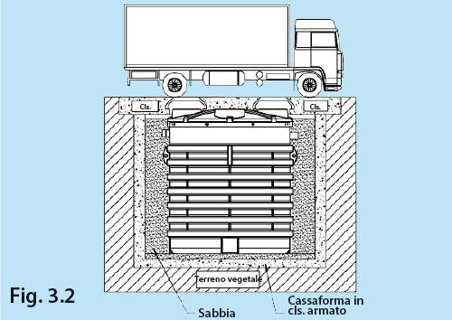
Image 1.1 - Prepare a suitably dimensioned hole with a flat bottom, leaving a 30/40 cm space around the tank. In presence of heavy grounds (ex: clay substrate ) and/or surface groundwater this distance must be increased to at least 50 cm. Lay a sand layer higher than 15 cm onto the excavation bottom to ensure the tank lays onto a uniform and levelled basement. The excavation must be at least 1 m far from other constructions.
2 - RINFIANCO E RIEMPIMENTO
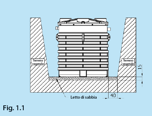
Image 2.1 - Lay the empty tank onto the excavation bottom sand layer , gradually fill the tank with water and contemporarily fill the outside with sand : subsequently proceed with gradual 15/20 layers filling the tank and then the outside with compacted sand . Never use sharp-cornered materials.
N.B. For laying into difficult locations (presence of groundwater, clay ground or slope) , see the paragraphs 2.6, 2.7 e 2.8.
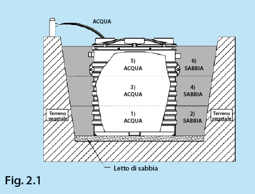
Image 2.2 - After having adequately filled and supported the tank, gradually cover it with vegetal ground for 20/30 cm, leaving the inspection holes free. The zone is therefore suitable for people passage and car passage is forbidden up to 2 metres from the excavation.
N.B. In case you wish to make the location suitable for car passage, see the chapter 3.
Extensions installation
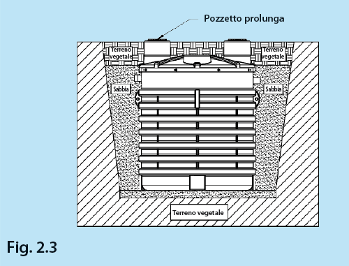
Image 2.3 - In case the tank has be grounded at a 30 cm depth while keeping its suitability for people passage, we advise to install the polyethylene extension wells directly onto the incoming and outgoing inspection holes. In case the tank must be positioned beyond the previously indicated height, a difficult condition we do not advise, please carefully follow the instructions specified into the Chapter 3 “car passage”. The technician will follow the indications contained into the two abovementioned paragraphs according to the installation depth
Biogas breather connection
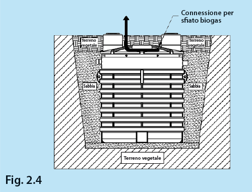
Image 2.4 - In order to prevent the forming of bad smells and therefore for the best installation performance, ALWAYS link a PVC or PE pipe (the diameter may vary according to the tank used) with the biogas exhaust predisposition into the tank cover. Bring the pipe onto the building’s highest point or in any case far from the habitation.
Wells installation
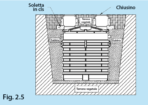
Image 2.5 - The installation of wells or shafts heavier than 50 kg is possible only if integral with the concrete slab in order to allow the even load distribution onto the tank. Avoid to build walled parts which may interfere with maintenance works or the substitution of the tank itself.
Laying in zones with groundwater
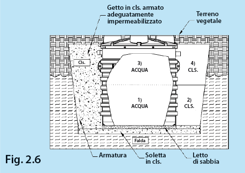
Image 2.6 - Surface groundwater is the riskier condition for laying an accumulation tank. In this case we recommend a thorough geotechnical report by a specialised technician. According to this report’s results, the technician defines the groundwater thrust level and therefore dimensions the best support and cover slab type ; particularly, he must design side supports with the necessary lift to resist heavy side thrusts. This resistance level may be further increased with the insertion of electrically welded nets. After having prepared a concrete basement onto the excavation bottom, lay another 10 cm sand layer to fill the corrugations into the tank basement . The tank and especially its side support must always be filled gradually. Therefore, we advise to fill half tank, contemporarily fill its sides with reinforced concrete and let it rest for 26/36 hours [Fig. 2.6 par. 1 e 2]. Subsequently finish the tank filling and side support [Fig. 2.6 points 3 e 4].
Laying in zones with clay ground
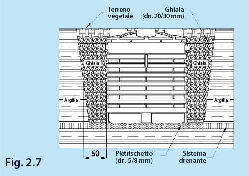
Image 2.7 - Clay round is another difficult condition for laying an accumulation tank. We recommend a thorough geotechnical report by a specialised technician also for this case . According to the report results, the technician in charge evaluates the round thrust lever, (high in case of clay ground) and dimensions the best support type . Particularly, the excavation bottom must be covered with a crushed stone/fine gravel layer (diameter 5/8 mm) and the tank sides must be supported with a gravel support (diameter 20/30 mm). The tank filling and side support operations must always be gradual as previously specified(see par. 2.1).
We advise also the insertion of a draining system onto the excavation bottom.
Laying with slope
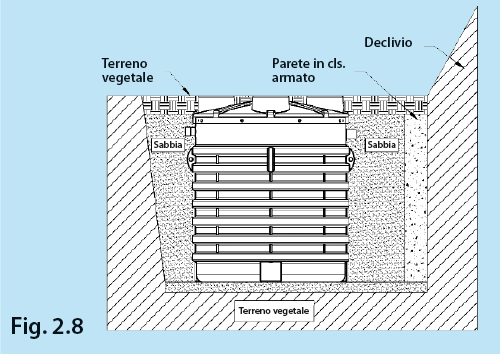
Image 2.8 - In case the tank is located near a slope or a declivity, it has to be surrounded by reinforced concrete walls, aptly dimensioned by a specialised technician in order to compensate for the round side thrusts and to protect the area from possible seepages . The tank filling and side support must be carried out gradually as previously specified (see par. 2.1).
3 - CAR PASSAGE
Vehicles passage - Class B125-EN124/95 - Max 12,5 tons
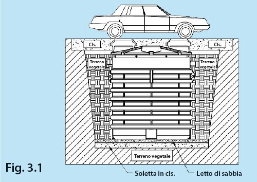
Image 3.1 - In order to make the location suitable for the passage of vehicles, build a suitable self bearing reinforced concrete slab , apt for the estimated passage weight and with a perimeter larger than the tank excavation. This prevents the structure weight from resting onto the tank. We advise to realise a 15/20 cm slab onto the bottom as well to fill the corrugations into the tank basement . The reinforced concrete self bearing slab and the concrete slab have to be dimensioned by a qualified technician. The tank filling and side support have to be carried out gradually as previously specified (See par. 2.1).
Heavy vehicles passage - Class D400-EN124/95 - Max 40 tons
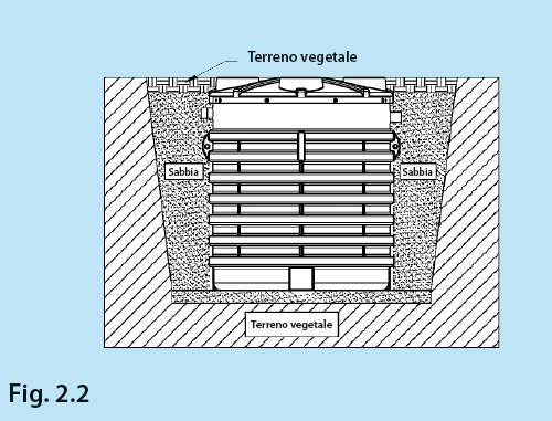
Image 3.2 - In order to make the tank suitable for the passage of heavy vehicles , realise a cast in-situ concrete formwork and a suitable concrete slab with a perimeter larger than the tank excavation, so that the weight rests onto the containment walls and not onto the tank. We suggest to lay a 100 cm sand layer onto the formwork bottom to fill the corrugation spaces at the tank basement. The formwork and the slab have to be dimensioned by a specialised technician. The tank filling and side support have to be carried out gradually as previously specified (See par. 2.1).
